Introduction | The Design Concept | Inertial Control Theory | Engine Performance Predictions | Compressor Performance Predictions | Proof of Principle Testing | Conclusions | References | Definitions, Acronyms, Abbreviations

Introduction | The Design Concept | Inertial Control Theory | Engine Performance Predictions | Compressor Performance Predictions | Proof of Principle Testing | Conclusions | References | Definitions, Acronyms, Abbreviations
Leakage modeling was based on simple orifice flow neglecting ball spin, with choked flow occurring at sufficiently high pressure ratios. An orifice coefficient Cd of 1.0 was used for conservatism, and for lack of available data. Leakage at the rotor/stator bearing was assumed zero, because bearing calculations indicated leakage could be controlled very well by altering rotor width (and thus bearing land width).
Combustion kinetics was simulated by a simple time lag for linear pressure rise to a level based on constant volume stoichiometric steady state combustion of gasoline (octane and air). Working gas thermodynamics was based on ideal gas laws with heat transfer. Steady state heat transfer was based on approximations of conduction and convection between working gas, ball piston, and cylinder/rotor, with cool intake air flow over the rotor exterior and the ball exposed outer hemispherical surface.
The model was simulated at constant rotation rate, simulating an engine load with substantial inertia. Output shaft torque per ball piston was the main output quantity, and also internal forces, pressures, and temperatures were output for review. The model was executed in a matrix mathematics program called Gauss [6].
Simulation Results - The four stroke rotor design was the main configuration of interest. The simulation model was exercised for a wide variety of cases considering different ball size, rotor size, leakage and heat transfer assumptions, and rpm. The optimized track design already discussed tended to narrow interest to larger balls, however, and that is the data to be presented.
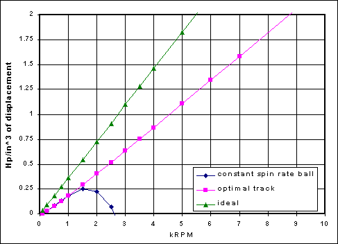
Figure 10 shows the specific power curves for the constant ball spin rate and optimal track cases (2 inch ball diameter, mean ball position radius=10.00 inch, 0.10 coefficient of friction). They are compared with a case of no friction, leakage, or thermal losses (but adiabatic pumping and estimated combustion loss is included). It can be seen how important the "inertial cancellation" of optimal track design really is. The constant ball spin rate power curve drops quickly as rpm reaches usable range due to inertial force growth. With the optimal track, the power curve is essentially linear (other factors may reduce power at high rpm, such as engine flow limitations).
 Figure 10. Specific power comparison for track designs (2 inch diameter silicon nitride ball, mean ball position radius=10.00 inch, 0.1 coefficient of friction, ball diametral clearance of 0.001 inch) |
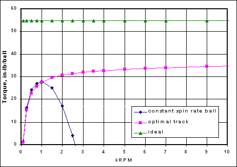
Figure 11 shows engine torque for the same cases, and the influence of leakage can be more readily seen at low rpm, where torque drops substantially below 1000 rpm. Above 1000 rpm, efficiency of about 60% is controlled by friction and thermal loss. Of the 40% loss, 20% is friction loss, 18% is thermal loss, and 2% is leakage. Leakage decreases with increasing speed, so efficiency increases slightly with speed.
 Figure 11. Torque comparison for track designs (2 inch diameter silicon nitride ball, mean ball position radius=10.00 inch, 0.1 coefficient of friction, ball diametral clearance of 0.001 inch) |
In comparison, typical losses for water cooled spark ignition engines [7] are 50-55%, of which about half is friction and half is thermal, with negligible leakage. The thermal losses have been greatly decreased in the new design by elimination of heat transfer to a water cooling system.
Design Choices - For the example engine, steady state temperatures were estimated as 700 degrees F for the cylinder/rotor and 2400 degrees F for the ball piston. To sustain that temperature, silicon nitride is chosen for the ball piston. Silicon nitride is also a good choice for light weight (lower centrifugal forces) and low friction, as well as low coefficient of thermal expansion.
With a silicon nitride ball piston and steel cylinder/rotor, which have widely different coefficients of thermal expansion, but also widely different steady state temperatures, the thermal expansion is almost perfectly matched. Thus, the material selection has a secondary benefit of maintaining operating clearance within 10-20% of nominal over a wide range of engine operating temperatures. In an actual engine development the thermal expansion can be tuned by rotor external design for cooling (cooling fins or outer rotor width, for example).
The use of a silicon nitride cylinder wall was considered, but friction of like ceramic materials is generally high. Research results concerning special silicon nitride compounds may be useful in production, however [8].
Note that it may be beneficial to introduce active lubrication into the engine. If friction can be reduced from 0.10 to 0.05, engine efficiency can be increased from 60% to 70%. There are trade-offs to be considered with active lubrication, including residue accumulation, emissions, and maintenance. One reasonable approach would be oil jet spray into the local cylinder wall contact area from the outside of the rotor, or oil pickup by the ball itself from the track area just before the power stroke.
|
Animated Web Demo | Software | Response Form |
Email: [email protected]
Web design &
hosting by 20/20
Technologies