
Introduction | The Design Concept | Inertial Control Theory | Engine Performance Predictions | Compressor Performance Predictions | Proof of Principle Testing | Conclusions | References | Definitions, Acronyms, Abbreviations

Introduction | The Design Concept | Inertial Control Theory | Engine Performance Predictions | Compressor Performance Predictions | Proof of Principle Testing | Conclusions | References | Definitions, Acronyms, Abbreviations
The mechanical dynamics of the design are conceptually simple, based on the 2-D equations of motion of an individual ball piston. Using Figure 4, assuming constant rotor rotation rate and simple Coulomb friction at the ball piston/cylinder wall contact, the three equations of motion are

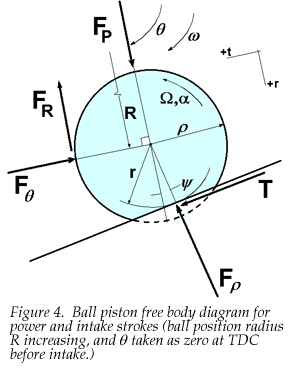
where the ball accelerations are

and ![]() is pressure force,
is tangential contact force,
is pressure force,
is tangential contact force, ![]() =
=
![]() is friction force,
is friction force,
![]() =d
=d![]() /dt,
/dt,
![]() =d
=d![]() /dt
(
/dt
(![]() is ball spin rate),
R is ball position radius,
r is rolling radius,
is ball spin rate),
R is ball position radius,
r is rolling radius,
![]() is friction coefficient,
m is ball mass,
is friction coefficient,
m is ball mass,
![]() is ball moment of inertia,
is ball radius, and
is ball moment of inertia,
is ball radius, and
![]() is track slope relative to tangential.
All kinematic quantities, including
is track slope relative to tangential.
All kinematic quantities, including ![]() ,
are known if rolling is assumed, so the three problem unknowns are
,
,
are known if rolling is assumed, so the three problem unknowns are
, ![]() , and T.
, and T.
One must be careful to keep sign conventions and direction of non-conservative friction forces correct while considering all phases of the engine cycle, and one reaches the important result of tangential force on the ball and imparted to the rotor in the clockwise sense,

| where | k = +1 if > 0 and k = -1 if < 0. |
For reasonable values of ![]() , the denominator of equation (3) is always positive, so the sign of can be determined from the numerator alone.
, the denominator of equation (3) is always positive, so the sign of can be determined from the numerator alone.
Earliest designs not based on engineering analysis used a dual contact track with maximum rolling radius (equal to ball radius) at TDC, changing in approximately sinusoidal manner to a small rolling radius at BDC. This design allowed for maximizing stroke and maximum compactness. In that case, coriolis forces and attendant frictional losses would negate the useful power from combustion/expansion at undesirably low rotor rpm.
Then sensitivity analysis of ball track design was studied using simple basic track geometry, i.e. sinusoidal variation of ball radius with rotation angle. It was thought that substantial reductions of inertial contributions to F![]() were achievable by "reversing" the track design so that full rolling radius was at BDC and a smaller rolling radius was reached at TDC, using a dual contact track. This approach was based on maintaining constant ball spin rate, which was thought to minimize inertial loads, and it was recognized that there would be some loss of stroke due to the track at TDC. It was found, however, that results were not much better, because of large coriolis forces that still existed.
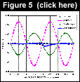
Figure 5 shows the individual contributors to rotor tangential force for an example of the constant ball spin rate track design. It is seen that the power producing force from combustion is dwarfed by the inertial loads, particularly the coriolis contribution.
were achievable by "reversing" the track design so that full rolling radius was at BDC and a smaller rolling radius was reached at TDC, using a dual contact track. This approach was based on maintaining constant ball spin rate, which was thought to minimize inertial loads, and it was recognized that there would be some loss of stroke due to the track at TDC. It was found, however, that results were not much better, because of large coriolis forces that still existed.
Figure 5 shows the individual contributors to rotor tangential force for an example of the constant ball spin rate track design. It is seen that the power producing force from combustion is dwarfed by the inertial loads, particularly the coriolis contribution.
Then sensitivity to rolling radius magnitude change was investigated by trial and error, and it was found that large improvements could be made by imposing a certain amount of ball angular acceleration in the proper direction to cancel coriolis forces. Figure 6 shows a comparison of net tangential forces for the simple constant ball spin rate track and optimized sinusoidal track. Inertial forces were decreased by almost an order of magnitude by this approach. The remaining force has about double the frequency, due to nonlinear ball track slope details that were not correctable by a simple sinusoidal track design.
Looking in more detail at equation (3), it is seen that along with the power producing contribution of ![]() , there are also tangential acceleration forces from both translation and rotation of the ball. We can take these contributions together and minimize them by using track rolling radius to impose ball angular acceleration
, there are also tangential acceleration forces from both translation and rotation of the ball. We can take these contributions together and minimize them by using track rolling radius to impose ball angular acceleration ![]() . We can define the inertial load we wish to eliminate by
. We can define the inertial load we wish to eliminate by

Now, ![]() is zero for constant speed operation, R, r, and
is zero for constant speed operation, R, r, and ![]() are dependent only on
are dependent only on ![]() , and
, and ![]() ,
, ![]() , and
, and ![]() are dependent only on
are dependent only on ![]() and spin rate
and spin rate ![]() due to the constraint of rolling. For example, the ball spin rate is
due to the constraint of rolling. For example, the ball spin rate is

Then differentiating with respect to time, the angular acceleration can be shown to be a separable function of ![]() and
and ![]() ,
,
![]()
Similarly, all other time derivatives can be separated, and using primes to denote derivatives with respect to ![]() , one obtains
, one obtains

 |
Thus, it is seen that for any rpm (![]() ), the geometry of the ball track (ball position radius R and rolling radius r as a function of rotation angle of the rotor) can be tailored to give exactly zero net force, by playing the ball angular acceleration against the ball translational acceleration.
Given R
), the geometry of the ball track (ball position radius R and rolling radius r as a function of rotation angle of the rotor) can be tailored to give exactly zero net force, by playing the ball angular acceleration against the ball translational acceleration.
Given R![]() ,
r
,
r![]() ,
and
,
and ![]() ,
then
,
then ![]()
![]() and
and ![]()
![]() can be fully computed. Using a dual contact track, allowing the ball rolling radius to change adds the degree of freedom necessary to achieve this balance. Figure 6 shows, for the "optimal" case, how inertial tangential forces are completely eliminated, leaving only the combustion force to provide usable power.
can be fully computed. Using a dual contact track, allowing the ball rolling radius to change adds the degree of freedom necessary to achieve this balance. Figure 6 shows, for the "optimal" case, how inertial tangential forces are completely eliminated, leaving only the combustion force to provide usable power.
It is important to point out that the resulting design is not a perpetual motion machine. The translational and rotational kinetic energy is simply exchanged in a prescribed manner to achieve the desired effect. In total absence of friction and other losses, the ball would roll around the track in perfect synchronization with the constant speed rotor without tangential interaction forces.
It is difficult to solve for the optimal geometry of the track explicitly, due to the trigonometric complexity of the governing equation (7). Iterative numerical methods, such as Newton Raphson, can be implemented to solve for the ball rolling radius, given a functional form for ball position radius. A logical assumption for R![]() is sinusoidal, but a different form useful for engine cycle optimization is just as easily used in the computation of r
is sinusoidal, but a different form useful for engine cycle optimization is just as easily used in the computation of r![]() . The track slope
. The track slope ![]()
![]() depends completely on R
depends completely on R![]() by the equation
by the equation
 |
 |
 |

so maintaining zero net force in equation (7) consists of solving a nonlinear transcendental equation for r![]() at discrete values of
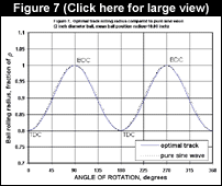
at discrete values of ![]() . Figure 7 shows an example of the optimal ball rolling radius variation with rotation angle for a 2.0 inch diameter ball with a mean ball position radius of 10.00 inches, and sinusoidal R
. Figure 7 shows an example of the optimal ball rolling radius variation with rotation angle for a 2.0 inch diameter ball with a mean ball position radius of 10.00 inches, and sinusoidal R![]() . Using the pure sine wave comparison in Figure 7, the form of r
. Using the pure sine wave comparison in Figure 7, the form of r![]() is seen to be nearly sinusoidal, but there are small nonlinearities introduced by track slope effects. Nevertheless, the track is readily producable using computer controlled machine tools.
is seen to be nearly sinusoidal, but there are small nonlinearities introduced by track slope effects. Nevertheless, the track is readily producable using computer controlled machine tools.
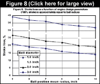
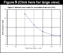
Note that the minimum rolling radius for this case is 0.81 at TDC, so a portion of the stroke available, 0.19 , is lost. One must iteratively choose a stroke, implicit in the definition of R![]() , and then check whether it is geometrically feasible for rolling radius at the end of the computation. Figure 8 shows the lost stroke as a function of ball size and ball position radius. Larger balls and ball track radii are better for minimizing stroke loss. Figure 9 shows minimum rotor radius as a function of ball size, based on a reasonable stroke loss of 25%. Less stroke loss can be achieved by using larger rotors, but there will be a practical design trade-off against centrifugal loads and engine size.
, and then check whether it is geometrically feasible for rolling radius at the end of the computation. Figure 8 shows the lost stroke as a function of ball size and ball position radius. Larger balls and ball track radii are better for minimizing stroke loss. Figure 9 shows minimum rotor radius as a function of ball size, based on a reasonable stroke loss of 25%. Less stroke loss can be achieved by using larger rotors, but there will be a practical design trade-off against centrifugal loads and engine size.
|
Animated Web Demo | Software | Response Form |
Email: [email protected]
Web design &
hosting by 20/20
Technologies